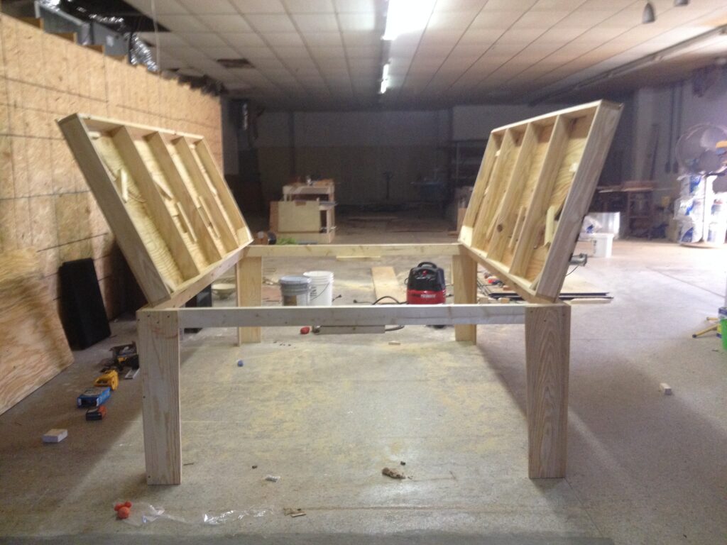
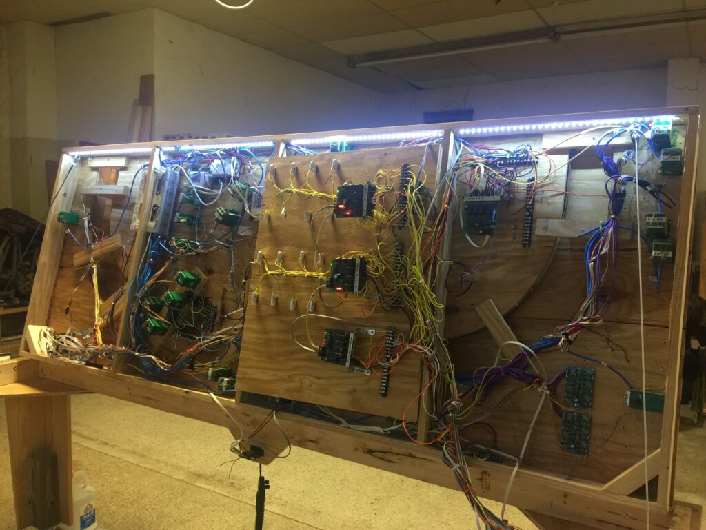
This is a 6′ X 8′ layout the table opens to each side. I did this to make working on the wiring easier. The tracks realign when the sides or closed by use of a shim system in the frame. It has Digitrax DCC system consisting of BDL168s, RX4s, SE8cs, PS2012, DS64s, PM42s, DT 400rs, and a DCS 200. I also used some Tam Valley Frog Juicers. I have several custom build boards for some of the features. The software I use to control the layout is Freiwald Train Controller Gold on a windows 10 PC.
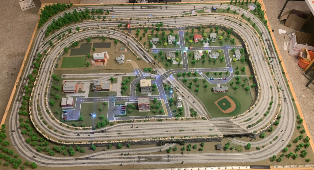
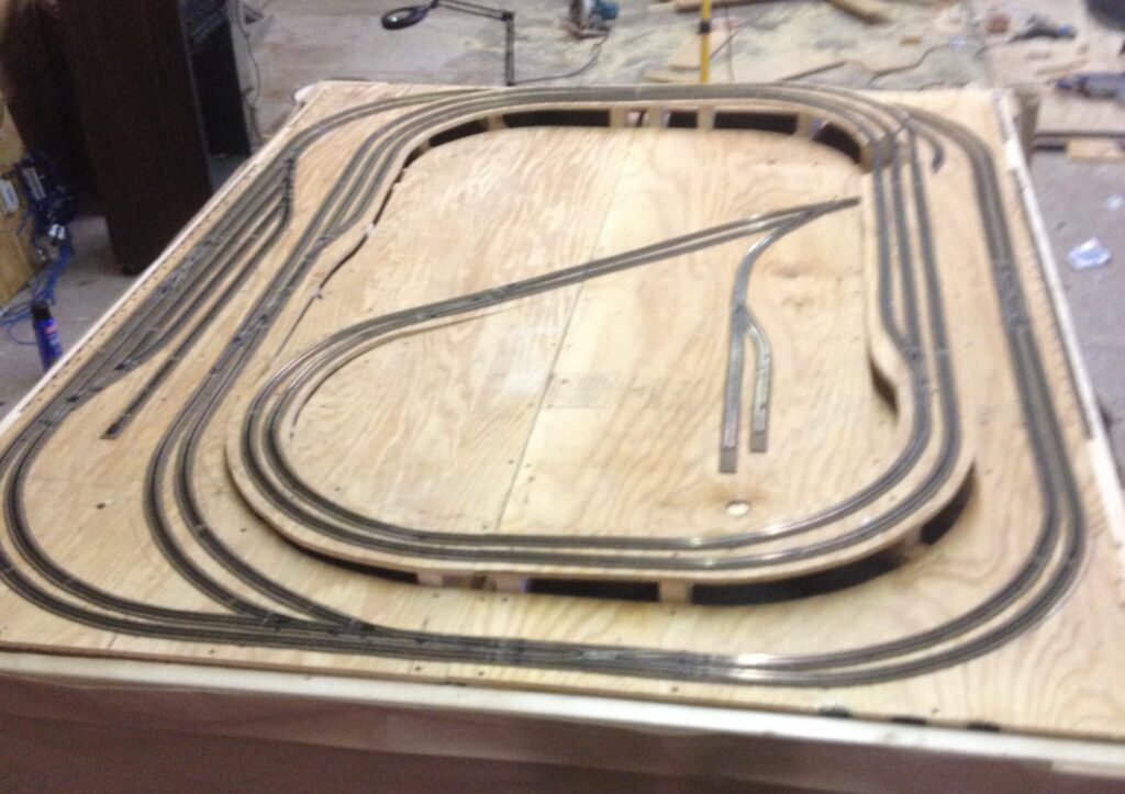
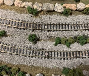
Below is a photos of the table open, and the table closed with most of the track laid.
Putting in the wiring the photos shown are layers 1 – 4. It will have a total of 6 layers of wiring when complete.
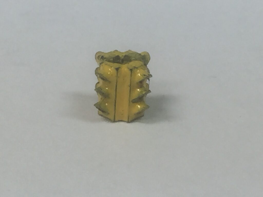
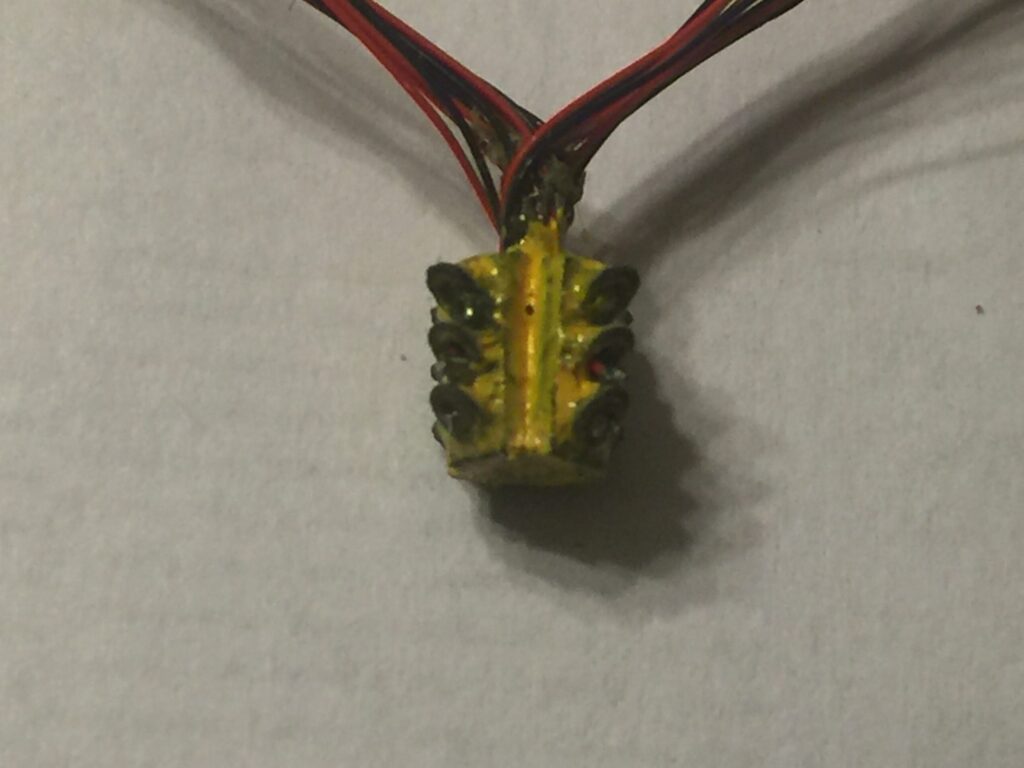
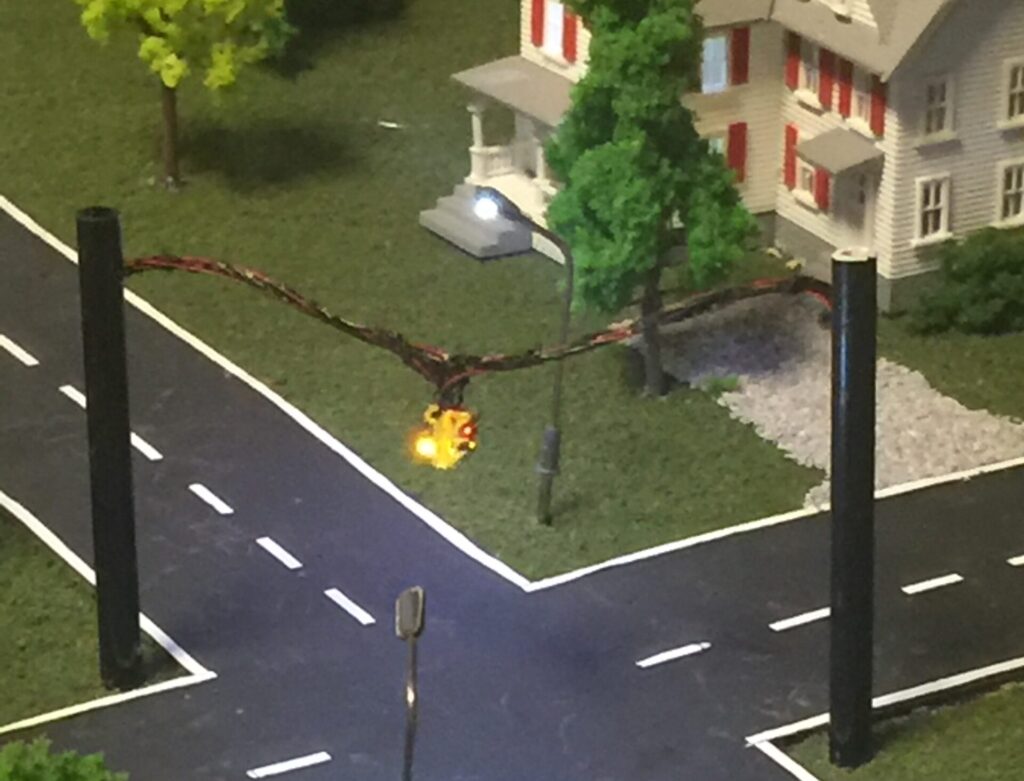
Printing and wiring an N scale traffic light. I have over 30 hours total in this project. I designed the print using Tinkercad. I learned quickly design the object much larger and scale it back to what you need. Then print it and make any correction needed. I used small drill bits to make the holes for the the wiring. Fishing the wires for the LEDs out the top took over 6 hours. It is controlled be a dual traffic light controller purchased from Amazon.
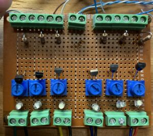
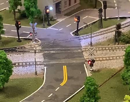
Getting the grade crossing to work. I used a NJ International grade crossing controller with the gateless crossbucks. When placing the sensors in the track I had trouble getting them to trigger reliably. That’s when I came up with the light an dark detectors posted on this site. I found the base idea posted on Youtube, and adjusted the values to get the desired response.
Below is a photo of the test board for the adjustable light and dark detectors this board can support 6 sensors. Next is the sensors placed in the track. I used the original sensors from the NJ International wiring harness and placed it and my LED in a piece of heat shrink tubbing to link the inputs. You can see that two fo the LEDs are currently on. Finally a photo of the crossing.
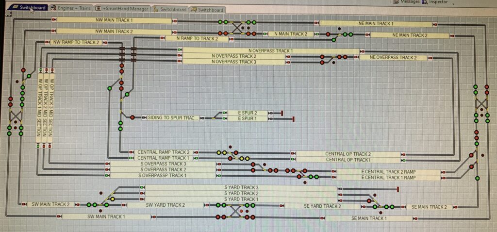
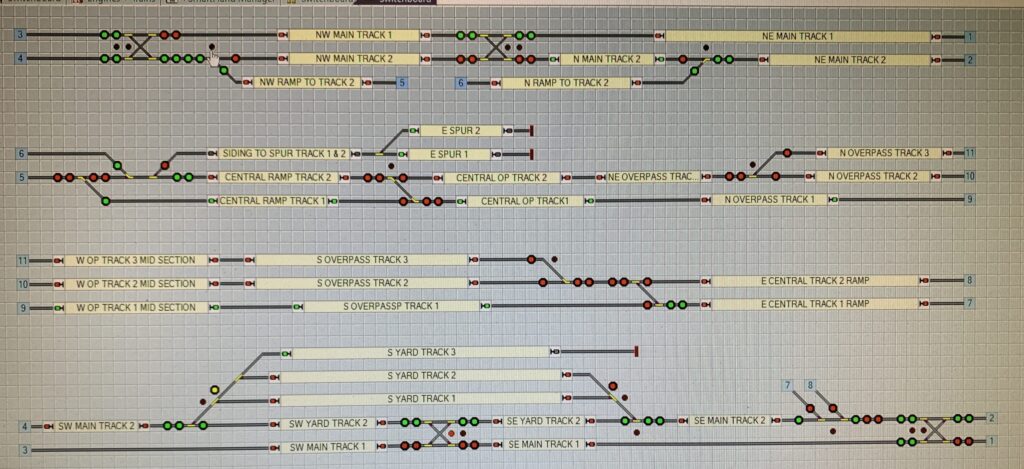
Controlling the trains from a computer using Railroad & Co Gold software. The layout devices communicate via LOCOnet. I use a LOCO buffer device to interface to the USB connection to the computer. The computer changes the signal colors based on the detection of rolling stock or locos on the layout. The layout has transponding and can ID the locos by cab number. The rolling stock uses resistor wheel sets. Below are two different views of the dispatcher display.